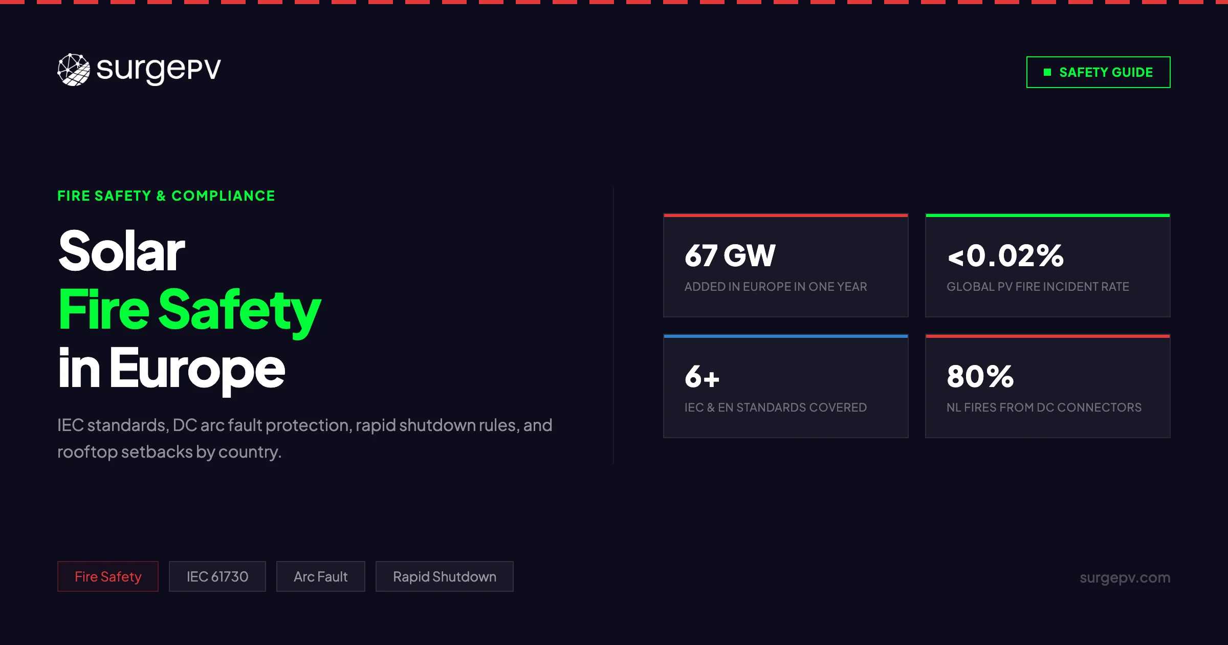
Europe added more than 67 GW of solar capacity in 2024 alone — and with rooftop installations proliferating on residential buildings, commercial warehouses, and industrial facilities across the continent, the fire safety of PV systems has moved from a niche technical concern to a mainstream regulatory priority. In the UK, fire services respond to a solar panel fire roughly every two days. In Italy, the national fire rescue service recorded a fire incident rate of approximately 0.45% across 550,000 PV systems between 2002 and 2015. In the Netherlands, research found that more than 80% of PV fire incidents traced back to a single root cause: poorly installed DC connectors.
These are not catastrophic numbers in absolute terms — solar fires remain rare events, estimated at fewer than 0.02% of all installations globally. But the consequences when they occur — rooftop penetrations that channel smoke into occupied buildings, DC circuits that remain live even after grid disconnection, and access routes blocked by panel arrays — create serious risks for occupants and fire brigades alike. As rooftop solar reaches millions of European homes and businesses, the technical standards and installation practices that govern fire risk matter more than ever.
This guide is the definitive resource on solar fire safety in Europe for 2026: the IEC and EN standards that apply, the DC arc fault and rapid shutdown technologies now entering European codes, rooftop setback requirements by country, and the installation practices that separate a genuinely fire-safe system from one that only looks compliant on paper.
TL;DR — Solar Fire Safety Europe 2026
The three most impactful steps for fire-safe rooftop solar in Europe: (1) specify modules certified to IEC 61730 with Class A or B fire rating; (2) use inverters or standalone devices with IEC 63027-compliant DC arc fault detection; (3) design rooftop layouts with fire brigade access pathways compliant with national setback requirements. Standards are tightening across DE, FR, ES, IT, and NL — installers who design to current requirements now avoid costly retrofits later.
In this guide:
- Latest fire safety regulatory updates across Europe (2025–2026)
- Why solar PV systems present unique fire risks — DC arcing, reverse current, insulation failure
- IEC 61730 module safety standards explained — components, classification, and testing
- IEC 62109 inverter safety requirements
- EN 50548 junction box standard and national equivalents by country
- DC arc fault detection and circuit interruption (AFCI) technology
- Rapid shutdown: European requirements versus NEC 2023
- Rooftop setbacks and fire brigade access requirements — country-by-country table
- Fire-safe installation best practices: conduit, MC4 connectors, string fusing
- How solar design software from SurgePV helps model fire-compliant layouts
Latest Fire Safety Updates: Solar PV Europe 2026
The regulatory environment for PV fire safety in Europe is evolving quickly. Several major updates have taken effect or been announced since 2024.
Fire Safety Regulatory Status — March 2026
| Regulation / Standard | Country / Scope | Status | Key Change |
|---|---|---|---|
| EN IEC 61730:2023 | EU-wide | In force | Updated fire classification; stricter module construction requirements |
| IEC 63027 (AFCI) | EU-wide (IEC) | Published — national adoption progressing | First dedicated standard for PV arc fault devices |
| VDE-AR-E 2100-712:2022 | Germany | In force | Updated disconnection and cable routing requirements |
| NF C 15-100 Amendment A4 | France | In force | Strengthened DC wiring routing rules for rooftop PV |
| UNE-HD 60364-7-712 | Spain | In force | Harmonised low-voltage installation requirements for PV |
| CEI 64-8/7 | Italy | In force | PV-specific electrical installation chapter with fire provisions |
| NEN 1010:2020 | Netherlands | In force | National low-voltage installation standard with PV annexe |
| FRISSBE BAPV Fire Safety Guideline | EU research project | Published May 2024 | First pan-European design guide for building-applied PV fire safety |
Key Changes Since 2024
IEC 61730:2023 edition now the certification baseline. The second edition of IEC 61730, published in 2023, introduced revised fire type classifications aligned with ANSI/UL 790 roof covering tests. From April 2025, some national incentive schemes require modules certified to the 2023 edition.
IEC 63027 AFCI standard published. The first international standard specifically governing arc fault circuit interrupters for PV systems is now published. Manufacturers including SMA, Fronius, and Hoymiles have certified AFCI products under this standard. European adoption into EN IEC 63027 is in progress.
FRISSBE project completed. The EU-funded FRISSBE (Fire Risks in Solar Systems for Building and Energy) research project published its Building-Applied PV Fire Safety Guideline in May 2024. This is the most thorough pan-European fire design guidance document currently available and is being referenced by national fire safety authorities.
Germany updates VDE-AR-E 2100-712. The 2022 revision of Germany’s PV application guideline tightened cable routing requirements, specifying that DC cables inside buildings must run in fire-inhibiting conduit, and strengthened firefighter labeling obligations.
Key Takeaway — Regulation Is Converging
While Europe still lacks a single unified PV fire safety code equivalent to the US NEC Article 690, the gap is narrowing. The FRISSBE guideline, IEC 63027, and updated national standards all point toward the same requirements: AFCI protection, fire-rated cable routing, firefighter access pathways, and module-level labeling. Installing to these requirements now is the safest path forward regardless of which country a project is in.
Why Solar PV Systems Present Fire Risks
Understanding the specific fire hazard mechanisms in PV systems is essential for selecting appropriate protections. Solar PV presents several risks that conventional AC electrical systems do not.
The DC Arc Fault Problem
The most dangerous fire risk in a rooftop solar installation is the DC series arc fault. Unlike AC circuits, where the current naturally crosses zero 50 times per second (giving arc faults a natural interruption point), DC circuits maintain a constant current. A DC arc fault, once initiated, will sustain itself and generate temperatures exceeding 3,000°C at the arc point — hot enough to ignite cable insulation, wooden rafters, and roofing membranes.
DC arc faults arise from several conditions:
- Damaged cable insulation from improper routing across sharp roof edges, animal damage, UV degradation, or mechanical abrasion
- Improperly mated MC4 connectors — connectors that are partially engaged, mis-matched between brands, or corroded create high-resistance joints that can initiate series arcs
- Loose screw terminals at junction boxes or combiner boxes
- Cracked or delaminated modules where internal cell connections have deteriorated
Because PV panels generate voltage even in low light, a damaged DC circuit can arc from sunrise to sunset seven days a week with no means of interruption — unless AFCI protection is present.
Reverse Current and Bypass Diode Failure
When one string in a parallel array produces lower voltage than adjacent strings — due to shading, soiling, or module mismatch — reverse current can flow through the weaker string. This can overheat modules, damage bypass diodes, and in severe cases cause thermal runaway in junction boxes.
Module-level bypass diodes are designed to protect individual cells, but they can fail short or open over time. A failed-open bypass diode means an entire cell group is excluded from the circuit; a failed-short bypass diode means the diode itself becomes a heat source. Either failure mode can initiate fires in the junction box region — the most thermally concentrated component on the back of a module.
Insulation Failure and Ground Faults
Transformerless inverters — now dominant in European residential and commercial markets because of their higher efficiency — connect the DC array directly to the AC grid without galvanic isolation. This architecture means that DC ground faults (where a live conductor contacts the mounting structure or earth) can result in stray currents flowing through unintended paths, potentially igniting combustible materials.
IEC 62109-2 and national standards require transformerless inverters to include ground fault detection, but the sensitivity of these detection circuits varies significantly between products.
Thermal Stress from Module-Roof Interface
Modules installed flush against combustible roofing materials (bitumen felt, timber decking) create enclosed air spaces that can reach elevated temperatures under normal operation. If a fault ignites within this space, the trapped heat dramatically accelerates fire spread across the roof surface. This is why fire brigade access pathways and setback requirements exist — not just for access, but to limit the continuous thermal envelope created by unbroken module arrays.
IEC 61730: PV Module Safety Standards Explained
IEC 61730 is the foundational safety standard for photovoltaic modules in Europe and globally. It is adopted in Europe as EN IEC 61730 and is required for CE marking of PV modules sold in EU markets.
Structure of IEC 61730
The standard comprises two parts:
IEC 61730-1: Requirements for Construction
Part 1 defines the minimum construction requirements that a PV module must meet to be considered safe for its application class. It covers:
- Electrical insulation materials and dielectric withstand requirements
- Protection against electric shock (creepage and clearance distances)
- Environmental protection (ingress protection rating)
- Mechanical construction integrity
- Junction box and connector requirements (cross-referencing EN 50548)
Part 1 defines three Application Classes for modules based on their installation context:
| Application Class | Description | Voltage Limit | Typical Use |
|---|---|---|---|
| Class A | Systems where live parts may be accessible | Up to 1,000 V | Residential and commercial rooftop |
| Class B | Systems in restricted access locations | Up to 1,500 V | Ground-mounted utility-scale |
| Class C | Systems integrated into buildings accessible to the public | Up to 1,000 V | Building-integrated PV (BIPV), public areas |
IEC 61730-2: Requirements for Testing
Part 2 defines the test sequence to verify conformity with Part 1. The test sequence includes:
- Electrical shock hazard tests (high-voltage isolation, dielectric withstand)
- Fire tests based on ANSI/UL 790 — the burning brand test, spread of flame test, and flying brand test
- Mechanical integrity tests (impact, hail, wind load)
- Environmental exposure (humidity freeze, UV preconditioning)
Fire Classification in IEC 61730
The 2023 edition of IEC 61730-2 classifies modules into three fire performance classes based on the ANSI/UL 790 test results:
| Fire Class | Burning Brand Test | Spread of Flame | Flying Brand Test | Typical Application |
|---|---|---|---|---|
| Class A | Pass — severe exposure | Controlled spread | No flying brands | Rooftop in high fire risk zones |
| Class B | Pass — moderate exposure | Moderate spread | Some brands, extinguish | Standard rooftop |
| Class C | Pass — light exposure | Limited spread | Limited brands | Low fire risk applications |
Most standard crystalline silicon modules from major manufacturers achieve Class C at minimum. High-quality frameless glass-glass bifacial modules typically achieve Class A or B. Glass-backsheet modules should be individually tested — the backsheet polymer type significantly affects fire class.
Pro Tip
When specifying modules for rooftop installations in Germany, France, or any jurisdiction with EN 13501-based fire class requirements, always request the IEC 61730-2 fire test certificate and confirm the specific fire class from the test report — not just from a product datasheet. “Tested to IEC 61730” on a datasheet does not specify which fire class was achieved.
EN 13501 and Its Interaction with IEC 61730
EN 13501 is the EU harmonised standard for fire reaction classification of construction products and building elements. PV modules installed on or in buildings may need to comply with both IEC 61730 (electrical safety) and EN 13501 (reaction to fire as a construction material).
The two standards use different test methodologies and do not map directly to each other. A module that achieves IEC 61730 Class A is not automatically EN 13501 Class A. In practice:
- Germany has interpreted EN 13501 strictly for BIPV applications, requiring B-s1,d0 classification or better
- France requires that modules on combustible substrates demonstrate fire reaction compliance under EN 13501
- Italy and Spain apply EN 13501 primarily to BIPV (building-integrated) rather than standard rooftop (BAPV) installations
IEC 62109: Inverter Safety for Solar Systems
IEC 62109 is the international safety standard for power converters used in photovoltaic power systems. It is adopted in Europe as EN IEC 62109 and is required for CE marking of PV inverters.
IEC 62109-1: General Requirements
Part 1 covers safety requirements applicable to all power conversion equipment for use in PV systems:
- Insulation coordination — minimum creepage and clearance distances to prevent tracking and flashover
- Protective earthing — requirements for earth continuity and protective conductor sizing
- Temperature limits — maximum surface temperatures for components accessible during normal operation
- Ingress protection — minimum IP rating requirements by installation environment
- Short-circuit and overload protection — internal fuse and circuit breaker requirements
IEC 62109-2: Inverter-Specific Requirements
Part 2 adds requirements specific to DC-to-AC inverters connected to public grids:
- Anti-islanding protection — mandatory detection of grid loss and disconnection within specified time limits; this is a fire safety measure because firefighters must be able to isolate a building from live electrical hazards
- DC injection limits — limits on DC current injected into the AC grid, preventing transformer saturation and overheating
- Ground fault detection — required for transformerless inverter topologies; must detect ground faults below 30 mA in some national implementations
- Disconnection means — requirements for AC and DC disconnect switches accessible to emergency services
Transformerless Inverters and Fire Risk
The vast majority of European residential and commercial inverters are now transformerless designs. These inverters are more efficient and less expensive than transformer-isolated designs, but they require more sophisticated ground fault detection because the DC and AC circuits share a common reference.
IEC 62109-2 Annex D provides guidance on ground fault detection for transformerless inverters, but minimum detection thresholds vary by national implementation. Germany’s VDE-AR-N 4105 and France’s UTE C15-712-1 each specify additional requirements beyond the base IEC 62109-2 text.
Key Takeaway — Inverter Certification
When evaluating inverters for European markets, confirm CE marking to EN IEC 62109-1 and -2, plus any relevant national grid connection standard (VDE-AR-N 4105 for Germany, UTE C15-712-1 for France, RD 244/2019 for Spain). A CE mark alone to IEC 62109 is necessary but not always sufficient for grid connection approval in every jurisdiction.
EN 50548 and National Standards — Country-by-Country Overview
EN 50548 governs junction boxes for photovoltaic modules — the components most frequently implicated in module-level fires. Understanding this standard and how it is applied nationally is important for component specification.
EN 50548: Junction Boxes for PV Modules
EN 50548 (adopted nationally as DIN EN 50548 in Germany, BS EN 50548 in the UK, CEI EN 50548 in Italy) specifies:
- Voltage and current ratings — junction boxes must be rated for the maximum system voltage (typically 1,000 V DC for Application Class A)
- Thermal performance — junction box housing must withstand operating temperatures without deformation or loss of IP rating
- Reverse current capability — bypass diodes and their connections must handle the reverse current levels specified by the module manufacturer
- Ingress protection — minimum IP65 for outdoor applications
- Connector compatibility — terminal dimensions and torque specifications for DC cable connections
- Corrosion resistance — metal parts subject to salt spray and ammonia exposure testing
The 2015 revision of EN 50548 tightened reverse current test protocols and added voltage drop measurement requirements to identify poor connections before installation. This revision was driven by investigation data showing that junction box connector failures were a leading cause of European PV fires.
National Standards Overview: Germany, France, Spain, Italy, Netherlands
Germany
Germany operates the most prescriptive PV electrical safety regime in Europe, combining IEC-based standards with national application guidelines.
| Standard | Scope |
|---|---|
| DIN VDE 0100-712 | Low-voltage electrical installation — PV systems; installation rules for DC wiring, string fusing, disconnection |
| VDE-AR-E 2100-712 | Application guideline; DC cable routing in fire-inhibiting conduit inside buildings; firefighter labeling |
| VdS 3145 | PV system fire protection guideline from Germany’s loss prevention and fire safety authority |
| DIN EN 50618 | DC cables for PV systems — flame retardancy and UV resistance requirements |
The VdS 3145 guideline, while not legally binding, is widely required by German property insurers and sets de facto standards for AFCI installation, connector quality, and fire brigade access pathway dimensions.
Firefighter labeling requirement: DIN VDE 0100-712 and VDE-AR-E 2100-712 together require that a schematic showing DC cable routing be made accessible to firefighters — typically a laminated plan affixed near the main distribution board and at roof access points.
France
France implements PV electrical safety through its NF C 15-100 low-voltage installation standard, with PV-specific supplements in UTE C15-712-1.
| Standard | Scope |
|---|---|
| NF C 15-100 (with Amendment A4) | General low-voltage installation requirements applicable to PV systems |
| UTE C15-712-1 | Specific guide for rooftop grid-connected PV installations — DC wiring, protection devices, disconnection |
| NF C 15-105 | Cable sizing and protection coordination |
France requires DC disconnection at the module string level for installations on residential buildings. UTE C15-712-1 specifies that DC cables must be routed in conduit when passing through habitable spaces and mandates a visible lockable DC isolator accessible at ground level for emergency services.
Spain
Spain harmonises EU standards through AENOR and applies PV-specific requirements through the Reglamento Electrotécnico de Baja Tensión (REBT) and its Instrucciones Técnicas Complementarias (ITCs).
| Standard | Scope |
|---|---|
| ITC-BT-40 (REBT) | Low-voltage electrical installation for electricity generation — applies to all grid-connected PV |
| UNE-HD 60364-7-712 | Harmonised Spanish adoption of IEC 60364-7-712 for PV installations |
| RD 244/2019 | Royal Decree on self-consumption — grid connection technical requirements including safety |
Spain’s REBT ITC-BT-40 requires PV installations to include a manual general disconnect switch on the DC side, accessible and identifiable for emergency services. Automatic disconnection on inverter fault is required, but AFCI is not yet mandated in national regulations, though it is increasingly specified by installers and insurers.
Italy
Italy implements PV electrical safety through its CEI (Comitato Elettrotecnico Italiano) national standards body.
| Standard | Scope |
|---|---|
| CEI 64-8/7 | General electrical installations standard — Section 7 covers special locations including PV |
| CEI 82-25 | Connection of PV generation systems to low-voltage public networks |
| CEI 0-21 | Technical standard for grid connection of active and passive users at low voltage |
CEI 64-8/7 requires PV installations to include DC series fuses at each string for arrays with more than two parallel strings. Inverters must include automatic disconnection on loss of grid signal (anti-islanding). Fire clearance around rooftop arrays on buildings above 12 m height is governed by national fire prevention standards, which may require specific setbacks depending on building occupancy class.
Netherlands
The Netherlands implements PV safety through NEN standards, with grid connection requirements managed by Netbeheer Nederland (the national DSO association).
| Standard | Scope |
|---|---|
| NEN 1010:2020 | Low-voltage electrical installation — includes PV annexe with DC wiring requirements |
| NEN-EN 50549-1 | Requirements for generating plants connected to distribution networks |
| Netbeheer NL technical conditions | Grid connection requirements for inverter-based generation |
Given the documented prevalence of DC connector faults as the primary cause of PV fires in the Netherlands, the Dutch industry association Holland Solar published installation quality guidelines specifically addressing MC4 connector installation torque, brand compatibility, and inspection requirements. These are referenced in NEN 1010 commentary and increasingly mandated in municipal permit conditions.
DC Arc Fault Detection & Circuit Interruption (AFCI)
DC arc fault detection is the single most impactful technology for reducing the risk of PV-initiated fires. Understanding how it works and what to specify is important for fire-safe design.
How DC Arc Faults Form and Propagate
A DC arc fault in a PV string begins when a conductive path is interrupted — by a damaged connector, a cracked solder joint, or a cable with compromised insulation. The interruption creates a small gap across which the DC voltage drives a plasma arc. Unlike AC arcs, the DC arc does not self-extinguish at a current zero crossing. Instead, it sustains itself, reaching temperatures of 3,000–6,000°C. At these temperatures, adjacent cable insulation vaporises and ignites; within seconds, the fire can spread to roofing materials.
A defining characteristic of series arc faults in PV systems is that they are electrically invisible to standard overcurrent protection (fuses and circuit breakers): the arc current is typically within the normal operating range of the string, so no overcurrent device trips. This is why conventional protection is insufficient and dedicated AFCI devices are necessary.
How AFCI Devices Detect Arc Faults
AFCI devices detect the characteristic electrical signature of DC arcs — high-frequency current ripple superimposed on the DC operating current — using algorithms that distinguish genuine arc faults from:
- Normal switching transients (inverter MPPT sweeps)
- Module shadow transitions
- String communication signals (power line communication systems)
When the AFCI algorithm identifies an arc signature that persists beyond its time threshold, it opens a relay or contactor to interrupt the DC circuit, removing the energy source from the arc and allowing it to extinguish.
IEC 63027: The AFCI Standard
IEC 63027 is the first dedicated international standard for arc fault detection devices for PV systems. It defines:
- Performance requirements for arc detection sensitivity and speed
- False alarm immunity requirements to avoid nuisance tripping
- Test methods for verifying AFCI function on PV strings
- Installation and configuration requirements
Microinverter systems can be certified under IEC 63027 when the inverter’s built-in arc detection meets the standard’s requirements. For string inverter systems, AFCI can be provided either by the inverter itself (most modern string inverters from SMA, Fronius, SolarEdge, and Huawei include integrated AFCI) or by an external AFCI device installed at the string combiner or DC combiner box.
AFCI Implementation Options
| Implementation | Description | Suitable For |
|---|---|---|
| Inverter-integrated AFCI | Arc detection built into string or microinverter firmware | New installations with AFCI-capable inverters |
| Module-level AFCI (per optimizer) | Power optimizer with per-module arc detection | Retrofit; enhanced granularity |
| External AFCI module | Standalone device at string input or combiner | Legacy inverters; retrofit |
| Rapid shutdown + AFCI combined | Devices that provide both shutdown and arc detection | High-risk installations, Germany VdS 3145 compliant |
Pro Tip
When specifying AFCI for a project, verify that the device’s false-alarm rate is acceptable for the array configuration. Systems with long string lengths (18+ modules), partial shading from trees or chimneys, or mixed module orientations generate more transient electrical noise — and cheaper AFCI implementations may generate nuisance trips that undermine owner confidence in the system. Request false-alarm performance data from the manufacturer for comparable array configurations.
AFCI in European Regulatory Context
As of early 2026, AFCI is not universally mandated in European national regulations, but the direction is clear:
- Germany: VdS 3145 (insurance and fire safety guideline) recommends or requires AFCI for most commercial installations; many German building insurers include AFCI as a condition of PV coverage
- Netherlands: Following documented connector fire incidents, AFCI specification is increasingly included in municipal building permit conditions for residential installations
- France: Not yet mandated but referenced in UTE C15-712-1 commentary as recommended for systems above 6 kWp
- Spain and Italy: Under consideration; no current national mandate but EU-level IEC 63027 adoption will accelerate national incorporation
Rapid Shutdown Requirements in Europe vs US NEC 2023
The concept of rapid shutdown — the ability to quickly de-energise a PV array’s high-voltage DC conductors to protect firefighters — was pioneered in US codes and is now receiving increasing attention in Europe.
NEC 2023 Article 690.12: The US Baseline
Under the 2023 National Electrical Code (NEC), Article 690.12 requires:
- Within the PV array boundary: DC conductors must be controlled to no more than 80 V within 30 seconds of initiating shutdown
- Outside the array boundary: Conductors must be controlled to no more than 30 V within 30 seconds
- Initiation: Shutdown must be triggered automatically on loss of grid power or by a manual initiating device accessible at the building service entrance
- Compliance pathways: Module-Level Power Electronics (MLPE) — microinverters or DC optimizers — or a listed PV Hazard Control System (PVHCS)
Exceptions exist for ground-mounted arrays and systems on non-enclosed, detached structures such as carports and pergolas, where firefighters are not expected to operate on the roof surface.
European Approach to Rapid Shutdown
Europe does not yet have a single standard equivalent to NEC 690.12. Instead, rapid shutdown-equivalent requirements are distributed across national electrical installation standards, fire codes, and building regulations.
| Country | Rapid Shutdown Equivalent Requirement | Standard / Source |
|---|---|---|
| Germany | DC disconnector accessible to fire brigade; DC cables in fire-inhibiting conduit inside building; labelled schematic required | VDE-AR-E 2100-712; VdS 3145 |
| France | Lockable visible DC isolator at ground level; automatic inverter shutdown on grid loss | UTE C15-712-1 |
| Spain | Manual general DC disconnect switch, identifiable and accessible | REBT ITC-BT-40 |
| Italy | Automatic disconnection on grid loss (anti-islanding); DC isolation means required | CEI 64-8/7; CEI 82-25 |
| Netherlands | DC isolator requirements per NEN 1010; grid connection conditions specify anti-islanding timing | NEN 1010:2020; NEN-EN 50549-1 |
The Gap Between Europe and the US
The fundamental difference between the European and US approaches is voltage reduction versus isolation. NEC 2023 requires that the voltage within the array boundary be reduced to 80 V or less — a level considered safe for bare-hand contact by firefighters wearing standard rubber gloves. European requirements generally require isolation (disconnection) rather than voltage reduction per se.
Isolation is meaningful for the DC circuits outside the array, but modules in sunlight will always regenerate voltage at their open-circuit voltage within milliseconds of disconnection — meaning isolated modules are still live at Voc even after a disconnect switch is opened. This is why the US approach’s voltage reduction requirement (through MLPE shutdown) is considered more protective of firefighter safety on the roof surface itself.
The FRISSBE BAPV Fire Safety Guideline (May 2024) explicitly recommends that European standards move toward voltage reduction requirements equivalent to the US approach, and several national fire safety authorities are expected to incorporate this recommendation into revised standards during 2026–2028.
Key Takeaway — Future Direction
Installers and EPCs designing rooftop systems that will remain in service for 25+ years should anticipate that European rapid shutdown requirements will tighten toward NEC 2023 levels during the lifetime of current installations. Specifying MLPE (microinverters or DC optimizers) or PVHCS-equivalent systems today future-proofs installations against regulatory upgrades and may be required for some insurance policies and commercial building certificates of occupancy within 3–5 years.
Rooftop Setbacks and Fire Brigade Access Requirements
Rooftop setbacks — clearance zones that must remain free of PV modules — serve two purposes: allowing fire brigades to access the roof without crossing energised arrays, and limiting the continuous thermal envelope that an unbroken array creates over combustible roofing.
Setback Principles
The IEA PVPS Task 12 report on Photovoltaics and Firefighters’ Operations established the foundational framework: firefighters approaching a burning building need to access the roof ridge for ventilation operations and need to traverse the roof from the access ladder to the fire location. Panel arrays that run edge-to-edge eliminate both capabilities.
Setback requirements vary significantly across European countries because fire safety on buildings is primarily a member state competence — there is no EU-wide building fire code.
Country Setback Requirements — Overview Table
| Country | Ridge Setback | Eave Setback | Side / Verge | Pathway Width | Source |
|---|---|---|---|---|---|
| Germany | 1.25 m (VdS 3145 recommendation) | 0.5 m in most Länder | 0.5 m | 1.0–1.25 m continuous access lane | VdS 3145; Länder building codes |
| France | Varies by commune; 60 cm lane commonly required | 0.5 m recommended | 0.5 m | 60 cm minimum pathway | Plan Local d’Urbanisme; UTE C15-712-1 |
| Spain | No uniform national requirement; local fire codes apply | Varies by municipality | Varies | Determined by local firefighting authority | REBT; local fire codes |
| Italy | 40 cm for systems above 3 kWp (general guidance) | 40 cm | 40 cm | 90 cm for multi-module rows | CEI guidance; fire prevention decrees |
| Netherlands | No uniform national setback; insurer requirements vary | Building permit conditions | Holland Solar guidance: 50 cm | Holland Solar: 90 cm | Holland Solar guidelines; NEN 1010 |
Germany: Detailed Setback Requirements
Germany’s fire access requirements for rooftop PV are primarily set at the Bundesland (state) level, meaning there is no single federal rule. However, the VdS 3145 guideline from the German fire prevention and loss prevention authority is widely adopted and referenced by insurers, municipalities, and building authorities.
VdS 3145 recommends:
- A 1.25 m clearance at the roof ridge running the full length of the building
- A continuous access pathway of at least 1.0 m width from any roof access point to each array section
- No panel installation within 0.5 m of roof edges or verges where fire brigade ladders may be placed
- Skylight and roof window clearance of at least 0.5 m on all sides
Individual German Länder (particularly Bavaria and Baden-Württemberg) have incorporated stricter setback requirements into their building codes for commercial and multi-family residential buildings. Installers must verify requirements with the local building authority (Bauordnungsamt) for any building above 7 m eave height.
France: Setback and Access Requirements
In France, rooftop PV setback requirements are primarily managed at the local level through the Plan Local d’Urbanisme (PLU). Many PLUs in fire-risk zones specify minimum clearance distances, and France’s national electrical guide UTE C15-712-1 provides general recommendations.
French requirements include:
- A 60 cm lateral access pathway is commonly required by PLUs for residential rooftops
- Modules may not obstruct access to roof windows (Velux), chimneys, or roof-mounted HVAC equipment
- For buildings subject to the Règlement de Sécurité contre les Risques d’Incendie (ERP classification), more stringent requirements apply including fire brigade consultation during design
Pro Tip
In France, always check the local PLU before finalising the rooftop layout. PLU requirements for solar setbacks vary significantly between urban communes (where fire brigade access is prioritised) and rural communes. A layout compliant with UTE C15-712-1 may still be rejected by a municipal authority with stricter PLU conditions.
Italy: Setback and Access Requirements
Italy’s setback requirements for rooftop PV are primarily governed by national fire prevention standards and CEI guidance documents. The general principle for systems above 3 kWp is a minimum 40 cm clearance on all edges and between module rows. For buildings above 24 m height (high-rise category under Italian fire law), additional requirements apply including consultation with the local fire brigade (Vigili del Fuoco) during design.
For industrial buildings, fire prevention requirements govern fire access requirements, and rooftop PV arrays may be subject to specific conditions in the certificate of prevention (CPI — Certificato di Prevenzione Incendi).
Netherlands: Insurance-Driven Setback Requirements
The Netherlands has no uniform national legislation on PV rooftop setbacks comparable to Germany or France. Instead, setback requirements are primarily driven by:
- Municipal building permits — many Dutch municipalities now include PV setback conditions in building permits
- Holland Solar guidelines — the industry association recommends 50 cm edge clearance and 90 cm access pathways
- Insurance conditions — Dutch property insurers, following the high incidence of PV connector fires, increasingly include setback requirements as conditions of PV system insurance
Key Takeaway — Permit Rejections
Industry data indicates that a significant share of rooftop solar permit rejections in Germany and France cite fire clearance or module placement errors as the primary reason. Designing setbacks correctly in the initial layout — before permit submission — is both a fire safety requirement and a project economics issue. Each revision cycle adds weeks to permitting timelines.
Fire-Safe Installation Best Practices
Standards and setback requirements define the minimum. Best practice installation goes further, addressing the root causes of PV fires through component selection, installation technique, and post-installation inspection.
MC4 Connector Installation and Compatibility
MC4 and MC4-compatible connectors are the most common single failure point in European PV installations. The connector junction creates a crimped and sealed contact between the module’s pigtail cable and the string wiring. Failures occur when:
- Connectors from different manufacturers are mated. Despite nominal compatibility, dimensional tolerances between brands can create high-resistance contacts. The IEC 62852 standard governs connector compatibility testing, but not all products are cross-tested.
- Improper crimping tool or crimp die is used. Each connector brand specifies a particular crimp tool and die set. Using an incorrect tool produces a crimp that passes visual inspection but has elevated contact resistance and reduced pull-out strength.
- Connectors are not fully engaged. The characteristic click of MC4 engagement does not always indicate full seating. Partially engaged connectors arc under load.
- Connectors are contaminated during installation. Dust, moisture, and cable lubricant on connector contacts increases resistance. Connectors should be installed with clean dry hands and the sealing boots fully engaged.
The Dutch fire investigation data linking 80% of PV fires to connector faults shows that connector installation quality is the single most impactful installation practice for fire risk reduction.
Required tools for proper MC4 installation:
- Brand-specific crimp tool with manufacturer-approved die set
- Torque-controlled stripper for cable preparation to correct strip length
- Pull-test device (minimum 50 N pull-out force per IEC 62852 factory test levels)
- Connector engagement verification process with visual confirmation
Cable Routing and Conduit Requirements
DC cables routing from the array to the inverter must be treated as continuously live circuits from sunrise to sunset, regardless of whether the inverter is operating. Cable routing best practices:
- Route DC cables in the shortest practical path to minimise exposed cable length
- Use cables rated to EN 50618 (TÜV 2 PfG 1169 equivalent) — specifically designed for PV DC circuits with UV resistance, flame retardancy, and extended temperature range
- Avoid routing cables across sharp roof edges, through or near HVAC equipment, or in contact with roof penetrations where thermal movement can abrade insulation
- Inside buildings: route DC cables in metallic conduit or in fire-resistant cable ducts compliant with national fire rating requirements (Germany requires fire-inhibiting conduit per VDE-AR-E 2100-712)
- Label DC cables at regular intervals and at all entry/exit points with their polarity and system voltage
String Fusing Requirements
For PV systems with more than two parallel strings, string-level overcurrent protection (typically fuses) is required by most national installation standards. String fuse sizing follows IEC 60364-7-712 guidance:
- String fuse rated current: at least 1.56 times the Isc of one string
- String fuse maximum interrupt capacity: greater than the maximum possible fault current from all parallel strings
- Fuse holders must be rated for DC voltage — AC-rated fuse holders fail catastrophically in DC circuits
DC-rated fuse holders and fuses carry distinct ratings markings (DC voltage, ampere, breaking capacity in kA DC). Using AC fuses in DC circuits is a dangerous and unfortunately common installation error that creates a circuit that appears protected but cannot safely interrupt DC fault currents.
Thermal Imaging Inspection
Thermal imaging (thermographic inspection) after commissioning and on a regular inspection cycle is the most effective method for identifying developing faults before they cause fires:
- Hotspot detection: Individual cells operating at significantly elevated temperature due to partial shading, cracking, or bypass diode failure
- Connection resistance: Junction boxes, combiner boxes, and string combiner connections with elevated resistance appear as localised hot spots
- Connector quality: Partially engaged or corroded MC4 connectors create measurable thermal signatures under load
- Inverter ventilation: Blocked inverter ventilation slots create overtemperature conditions detectable by thermal imaging
The FRISSBE guideline and VdS 3145 both recommend thermal inspection: within 12 months of commissioning, then every 4 years for residential and every 2 years for commercial systems, or following any significant weather event such as hail or storm.
Mounting and Ventilation
Flush-mounted installations (no air gap between modules and roof surface) concentrate heat and limit natural cooling. Where roof structure allows, a minimum 10 cm air gap under the module array is recommended to:
- Reduce module operating temperature (improving efficiency and reducing thermal stress)
- Limit heat accumulation that could sustain ignition of roofing materials
- Allow drainage of water and debris that would otherwise accumulate under modules
For installations on flat roofs using ballast systems, ensure that cable routing does not create cable penetrations into the roof membrane that could admit water, and that module-to-module spacing provides ventilation across the entire array footprint.
Using solar software that models the thermal environment of a rooftop layout — including the interaction between setbacks, ventilation gaps, and array density — helps identify high-risk configurations before installation rather than after.
Design Fire-Compliant Solar Layouts in Minutes
SurgePV’s solar design software automatically applies rooftop setback rules, flags AFCI requirements, and generates fire-access pathway diagrams for permit submissions — across Germany, France, Spain, Italy, and the Netherlands.
Book a DemoNo commitment required · 20 minutes · Live project walkthrough
How SurgePV Helps with Fire Safety Compliance
Designing a fire-compliant rooftop PV system requires navigating at least three distinct layers of requirements simultaneously: module-level fire ratings, electrical protection standards, and rooftop access geometry. Most design tools handle one of these layers adequately; very few handle all three.
SurgePV’s solar design software is built specifically for European installers and EPCs who need to produce permit-ready designs that satisfy the local authority having jurisdiction on the first submission.
Setback and Access Pathway Design
SurgePV’s rooftop design canvas includes configurable setback rules that can be set per project to reflect the applicable national and municipal requirements — Germany VdS 3145 setbacks, French PLU minimum pathways, Italian 40 cm edge clearance. When you place module strings on the roof surface, the software automatically enforces the active setback profile and flags any placement that violates the clearance rules before the design is finalised.
This matters practically: the shadow analysis required to maximise yield often pulls designers toward placing modules as close to ridge and edge as possible — into exactly the areas that setback rules protect. Having setback rules actively enforced in the same tool that performs solar shadow analysis software prevents the conflict from surfacing only at permit review.
Electrical Protection Specification
SurgePV’s string sizing and electrical design module includes AFCI compatibility flags for the inverter database. When you select an inverter without integrated AFCI, the software flags this and prompts specification of a compatible external AFCI device. The generated single-line diagram includes the AFCI device in its correct circuit position, producing documentation that satisfies the installer’s compliance obligation.
String fuse sizing follows IEC 60364-7-712 methodology automatically — the software calculates the required fuse rating from the selected module’s Isc and the number of parallel strings, and checks the specified fuse against DC voltage and interrupt capacity requirements.
Firefighter Documentation
Every permit submission in Germany and several other jurisdictions requires a firefighter schematic showing DC cable routing, disconnect switch locations, and string labeling. SurgePV generates this document automatically from the completed system design, formatted to the conventions expected by German building authorities and consistent with VDE-AR-E 2100-712 labeling requirements.
Proposal and Financial Modelling
Fire-safe design adds cost: AFCI devices, premium cables, conduit, and professional connector installation all contribute. SurgePV’s solar proposal software integrates these line items directly from the system design, so the cost of compliance is transparent in the client proposal rather than absorbed as margin erosion after contract signature.
For European projects where energy yield modelling drives financial viability assessments, the generation and financial analysis built into SurgePV accounts for the yield impact of setback-driven module exclusion zones — ensuring that the financial model presented to clients reflects the actual deployable array, not an optimistic estimate that will be revised at design stage.
For a broader look at how European solar policy is shaping installation requirements, see our guides on solar energy policies in Europe and European solar incentives.
Conclusion — Three Action Items for Fire-Safe Solar Design in Europe
Solar fire safety in Europe in 2026 is a domain of real and tightening requirements, where the gap between compliant and non-compliant installations has tangible consequences — for building occupants, for fire brigades, and for installers who face liability exposure when fires occur in systems they designed and installed.
The standards picture is complex but navigable. IEC 61730 and IEC 62109 provide the module and inverter safety foundations. EN 50548 governs junction boxes. National electrical installation standards (DIN VDE 0100-712, UTE C15-712-1, REBT ITC-BT-40, CEI 64-8/7, NEN 1010) govern installation practice. And IEC 63027 AFCI requirements are emerging as the next tier of mandatory protection across Europe.
Three actions to take from this guide:
-
Specify fire class and AFCI in every project. Every module specification should include the IEC 61730-2 fire class from the actual test certificate. Every inverter specification should include AFCI capability — integrated or external via IEC 63027-compliant device. These specifications cost little in project planning and substantially reduce fire risk and liability exposure.
-
Design setbacks before optimising yield. Rooftop layouts should begin with the applicable national setback profile applied to the available roof area, with the accessible module area identified before string sizing begins. This prevents the common error of designing a maximum-yield layout that fails at permit stage due to fire access violations.
-
Use solar software that enforces compliance by design. Manual checking of setbacks, fuse ratings, AFCI requirements, and firefighter documentation against multiple national standards in parallel is error-prone and time-consuming. The right solar design software automates these checks and generates compliant documentation as a natural output of the design process — converting compliance from a cost centre into a competitive advantage.
Frequently Asked Questions
What is IEC 61730 and why does it matter for solar panels in Europe?
IEC 61730 is the international safety standard for photovoltaic modules. Part 1 covers construction requirements and Part 2 covers testing procedures including fire resistance. In Europe, it is adopted as EN IEC 61730 and is mandatory for CE marking and market access. Modules must meet Class A, B, or C fire ratings — Class A providing the highest resistance.
Is rapid shutdown mandatory for solar PV systems in Europe?
Rapid shutdown is not yet uniformly mandated across all EU member states the way it is under NEC 2023 Article 690.12 in the United States. However, Germany’s VDE-AR-E 2100-712 requires disconnection means at specified points, and several national fire codes require firefighter access protocols that effectively mandate equivalent functionality. The trend across Europe is toward stricter rapid shutdown-equivalent requirements.
What is DC arc fault protection and which inverters support it?
DC arc fault protection (AFCI — Arc Fault Circuit Interrupter) detects dangerous electrical arcs in DC wiring and shuts down the system before fire can ignite. IEC 63027 is the international standard for AFCI devices on PV systems. Most modern string inverters from SMA, Fronius, Huawei, and SolarEdge include integrated AFCI. For older string inverters, standalone AFCI modules can be retrofitted.
What are the rooftop setback requirements for solar panels in Germany?
Germany’s fire safety setback requirements vary by state (Bundesland) and building type, but widely adopted guidance calls for a 1.25 m ridge clearance and defined access pathways. The VDE-AR-E 2100-712 application guideline specifies module arrangement and labeling requirements to facilitate firefighter operations. Commercial buildings typically require wider clearance zones than residential installations.
What caused most solar panel fires in Europe?
The majority of solar PV fires in Europe have been caused by DC-side faults: faulty or improperly seated MC4 connectors, damaged DC cable insulation, and series arc faults in string wiring. In the Netherlands, poorly installed DC connectors accounted for more than 80% of fire incidents studied. Inverter faults and AC-side issues are a secondary cause. Proper connector installation torque, cable routing, and AFCI protection together address the root causes.
How does IEC 62109 apply to solar inverters?
IEC 62109 (Parts 1 and 2) defines safety requirements for power converters used in photovoltaic power systems. Part 1 covers general requirements including insulation, protective earthing, and temperature limits. Part 2 covers inverter-specific requirements including anti-islanding and disconnection. CE-marked inverters sold in Europe must comply with EN IEC 62109, making it a baseline certification requirement for all grid-connected PV inverters.